RSSNewsFeeder
Member

A must-have tool when shooting the night sky is a remote release trigger for your camera. Triggers range from very simple cable releases over phone apps that connect to your camera’s Wifi, to very specialized Intervalometers. I wanted to build something even better…
I tried the phone apps for my cameras and they miss a very basic feature: bulb mode timing. Meaning, when you set the camera to bulb mode and start the exposure, most apps do not display how long the shutter is open already. It also eats battery life from the camera as Wifi or Bluetooth needs to be on on the camera. In the mid-range there are Intervalometers that can be programmed through a small display and some buttons and usually work quite well.
But what if “quite well” is not enough?
There are quite some commercial products available which sound nice on paper, but for me they offer too much options which I mostly will never use. Also, they are often quite expensive.
On the other end there are cheap offerings, but then they lack a feature that I would like to have. I have of course not tried all remote timers, but I tried some and none of them really fit my needs. The most annoying thing for instance is not being able to light up the display of a timer while it is running.
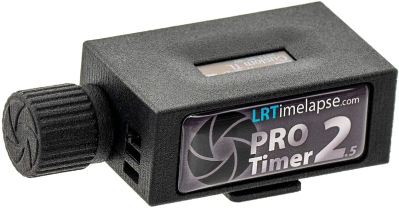
The only off the shelf Intervalometer that looks like a winner is the LRTimelapse Pro Timer 2.5. With a price of around 175 Euros (~$206 USD) it is not on the cheap side, but I guess it’s worth every cent. Gunther Wegner, the man behind LRTimelapse also has a very nice tutorial on how to build your own Intervalometer, which exceeds my build by miles in terms of features.
What are my options?
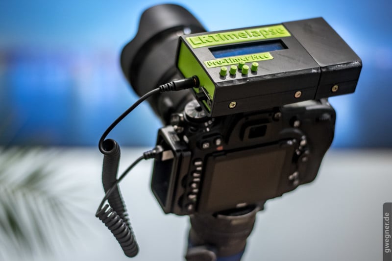
I could have just built a LRTimelapse Remote Timer Free but I dislike the 2×40 Display, the outdated Arduino Uno and the size of it. There are smaller Versions now available through the LRT Forum but the one I am interested in, is closed source at the moment, and that doesn’t fit my style. If I build something, I also want to mess around with the code.
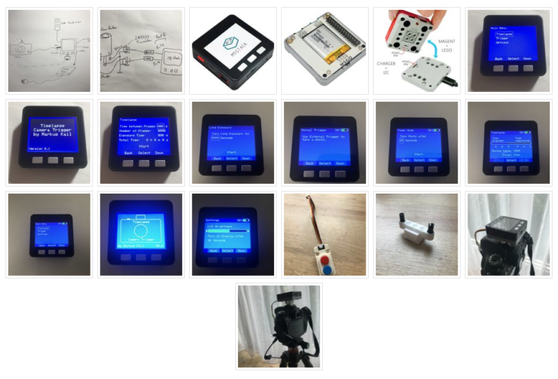
While looking for other options I came across a project from Markus Kail, which looked promising. A small enough housing with integrated lcd, buttons, battery and charging circuit. I contacted Markus to get the Arduino code, since the link was broken on his website and he showed me the current status of his timer, which looks really polished with really nice graphics and super sleek user interface. Markus was kind enough to send me this version and I installed it on my just delivered M5Stack.
It looks just stunning, has a very powerful preset system and is very easy to set up as it calculates movie lengths, times, etc. for a very good experience when using the timer for it’s main purpose: TimeLapse shooting. (The pictures above do not show the current state of his Timer.)
My main issue
“My issue” explicitly, because there is nothing wrong with those products. Either self built, or commercial. They just don’t fit me, because my needs are special (read: strange)
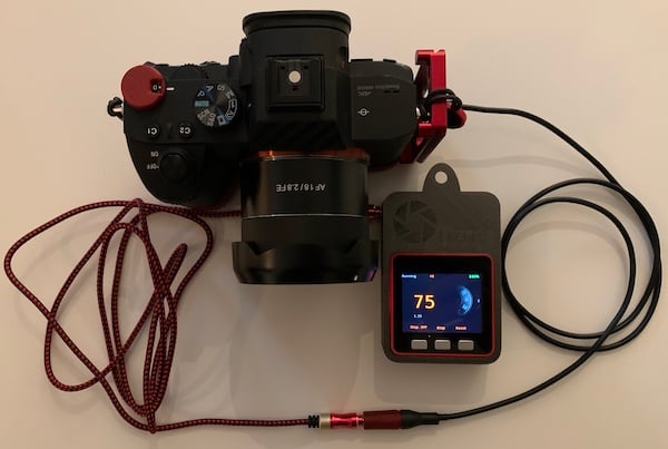
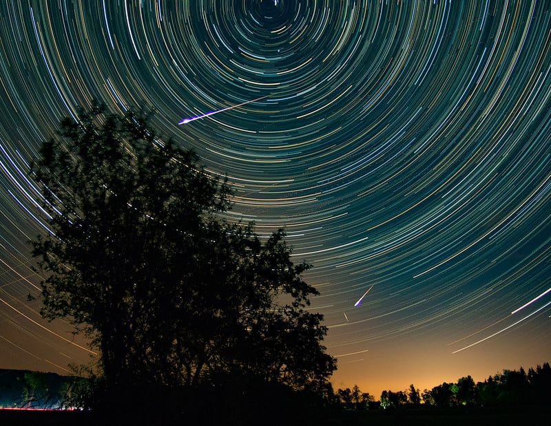
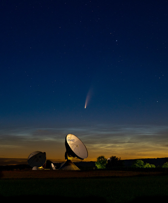
In my case, the intervalometer is not used to shoot Timelapse and create a Timelapse video out of it. My timer gets used in the dark when hunting for the stars, the milky way or meteor showers. I shoot stacks of pictures for noise reduction, for composite pictures of meteors, or for creating star trail pictures. When mounted on my MSM Star Tracker I want to have total control over the first few exposures to dial in my settings.
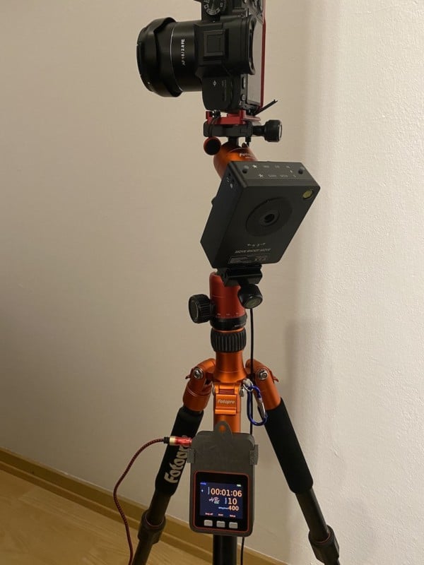
If you don’t know the Move Shoot Move Star Tracker make sure to check it out, as it is an amazing small device that makes polar alignment easy. I have successfully shot 4 minutes subs without any trailing. (If you use the coupon code “DIRK” at checkout, you will get 5% off from your complete purchase).


Back to the drawing board
To make a product that suits me, I first need to get my requirements:
- Start-Stop Bulb Mode
- Timed Shooting
- Graphical, lit display
- Settings survive a reset
- Universal for all my cameras
- USB chargeable
- Small, but not too small in terms of display size
- WiFi or Bluetooth for later updates (remote trigger for lighty)
Source: https://xkcd.com/730/
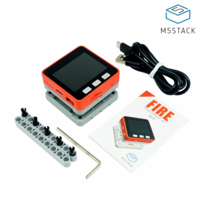
As I had already the M5Stack lying around, and it ticks the boxes for usb charging, display and size, I thought I would reuse it. In addition I would only need a small breadboard to create the electronic for the camera trigger and some wires to build my adapters.
Here is the complete list of things I used to build timy (sans 3D printed parts)
Of course you need a cable that suits your camera, or like I did, just use the cable from a timer that I already had.
Total cost: about 50 Euro, or $60 USD.
The Code
I first tried to program with the amazing M5ez library, but the M5Stack has a very neat feature that I wanted to keep. If you use UIflow, the code can be updated wirelessly. You can also have more than one script on the M5Stack and select the desired program during startup.
Uiflow is a bit different, as you “program” your code using predefined blocks and UIflow creates micropython code out of it. Not every function from micropython is implemented in UIflow, but you can get around this using custom ‘execute’ blocks and write your own code.

UIflow Coding
To make the M5Stack listen to keypresses while counting I used micropythons inbuilt _thread library which sadly is not available as a predefined block. Variables in UIflow are always set to global, which is one thing to keep in mind if programming. With UIflow and the concept of updating your code wirelessly you can get really fast results and try them out very quickly.
It also features an UI Editor, so no more guessing how the end result will look like.
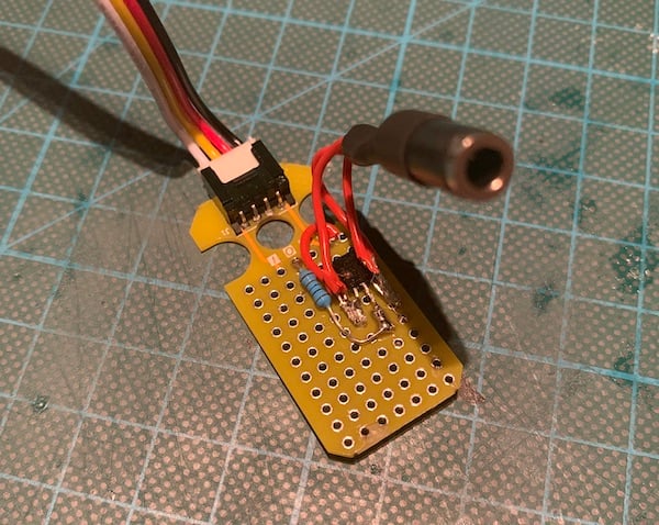
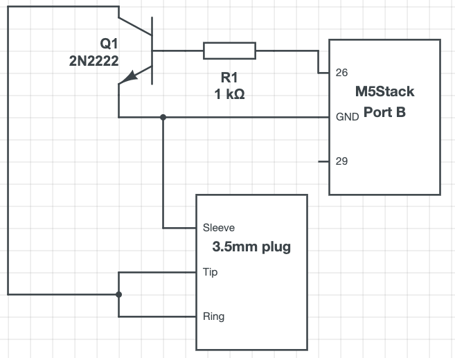
Electronics
To connect the shutter to ground I used a small breadboard and soldered together the following schematics. If you want to control the focus pin of the camera through software, you can use pin 29; I don’t need autofocus, so I simply connected the focus and shutter pin together to pin 26 of the M5Stack.
Case
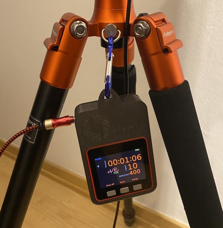
To make everything fit together neatly I designed a case and 3d printed it in PLA. Everything fits together without screws, the lid just slides onto the bottom of the case.
To support the M5Stack at the top, I just turned off elephant foot compensation in PrusaSlicer. This creates a very small lip to prevent the M5Stack from falling out at the top. Everything prints without supports and fits together snuggly. The case also has a carabiner mount to attach it to a tripod if you dislike the other mounting options.
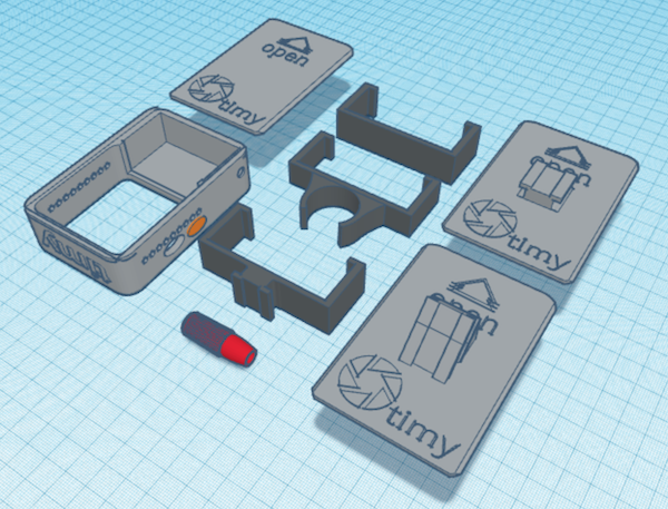
If you need to make edits to the mounts or have other ideas for your own case, my design is available on Tinkercad.
How it works
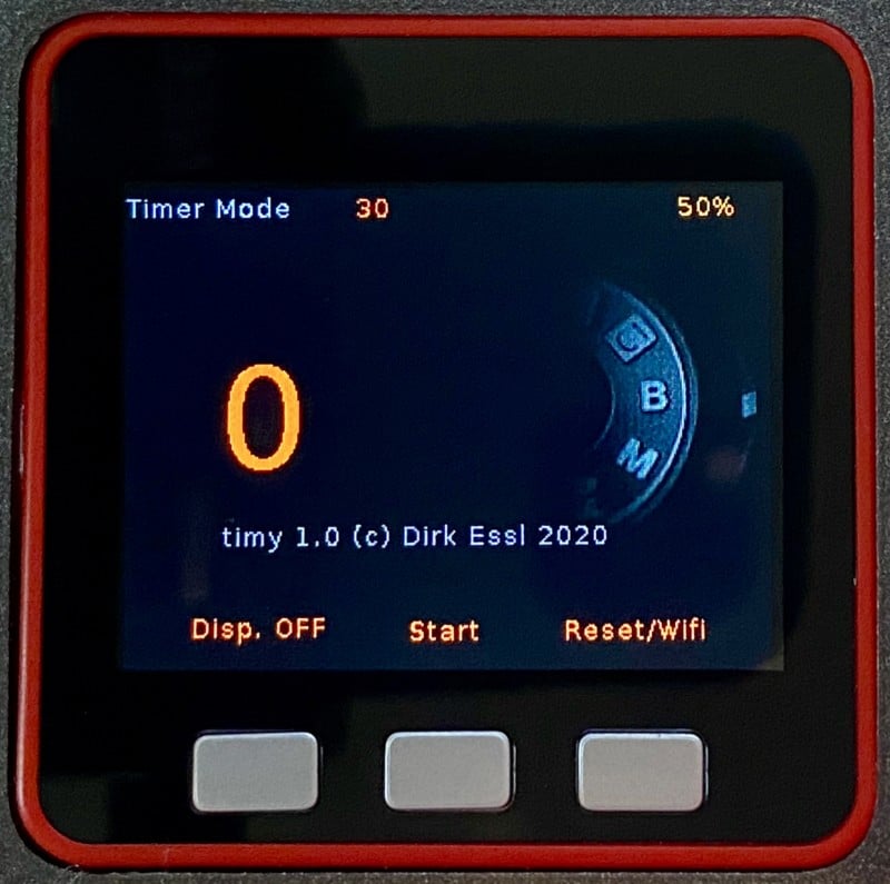
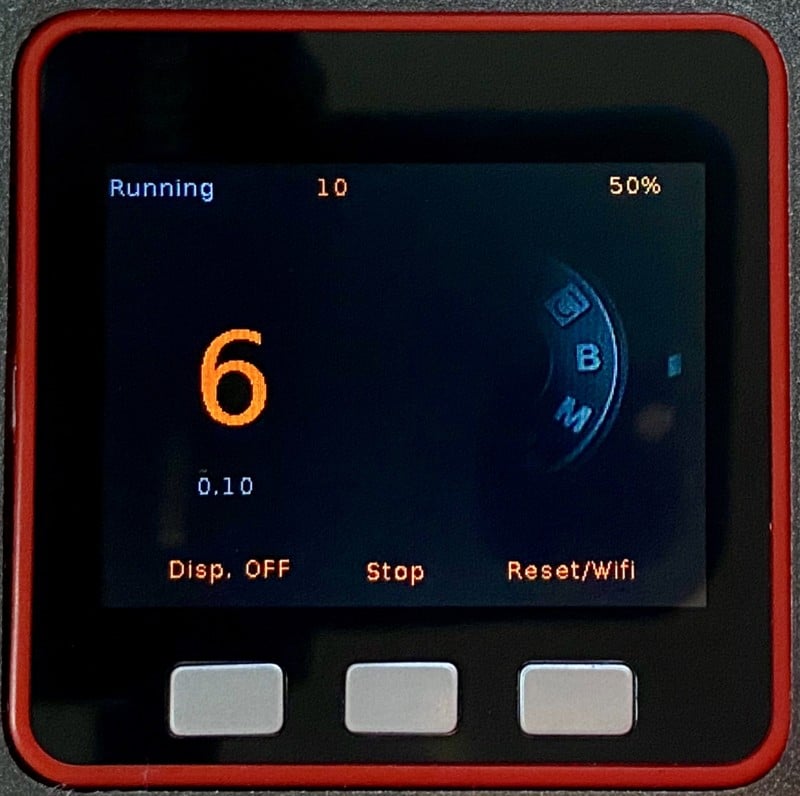
timy currently has two modes:
Bulbmode – I use this to get my baseline Exposure and to compose the camera for later timed shoots. I usually shoot at a higher ISO and then calculate the right time for my lower ISO shots. It can also be used as a remote trigger in this mode. Easiest mode ever.
Press Start to open the shutter, Stop to close the shutter. Stop is actually Pause. The Reset Button then resets the time to zero. The Display can be turned off when running to save battery. The LED bars on the side show a Knight Rider light while running.

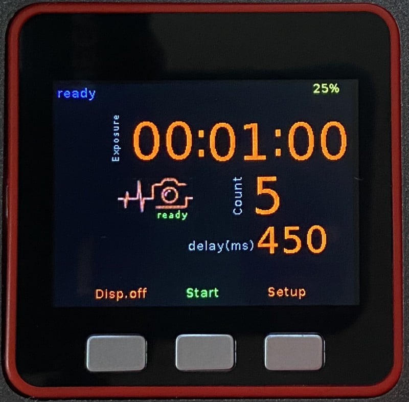
Timelapse Mode – Although not really used for TimeLapse in my case, it can be used to shoot TimeLapse, but is only made for Bulb Mode Timelapses beyond 1 seconds Exposures. If there is need for a classic TimeLapse Timer, it’s easy enough to implement.
All Settings are saved in EEPROM and survive a reset/reboot. The delay setting is mainly to give the camera enough time to save the picture to the SD-card and only really matters on sub 10 second exposures. If exposing for minutes, a zero millisecond delay setting will not really matter and will take picture after picture as fast as possible.
Initial Screen
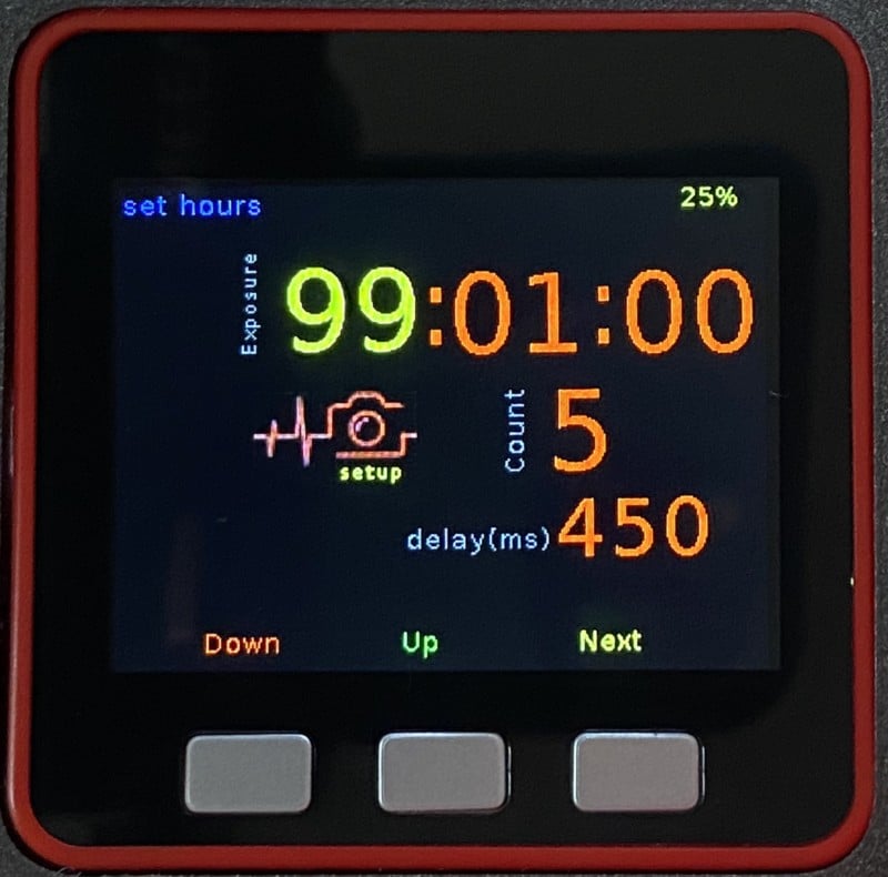
Set Hours
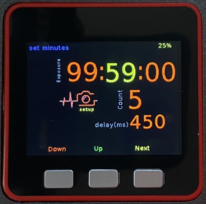
Set Minutes
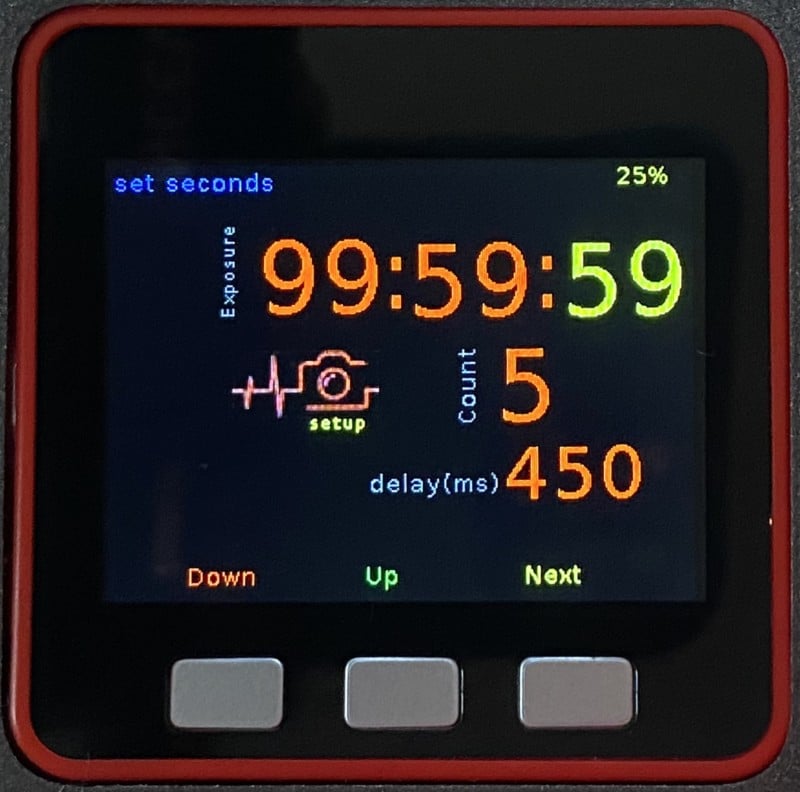
Set Seconds
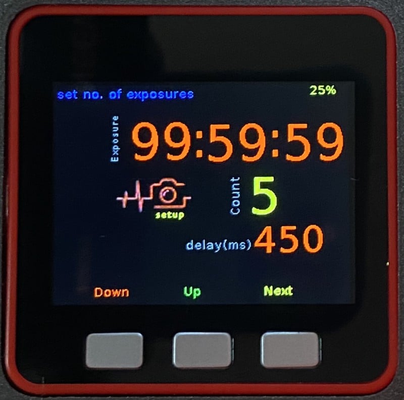
Set Number
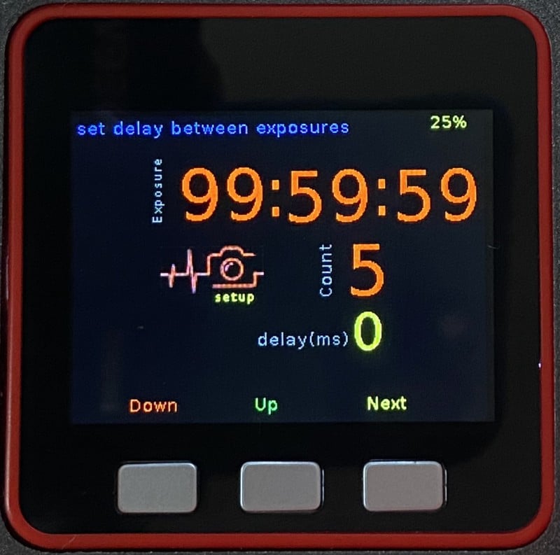
Set Delay
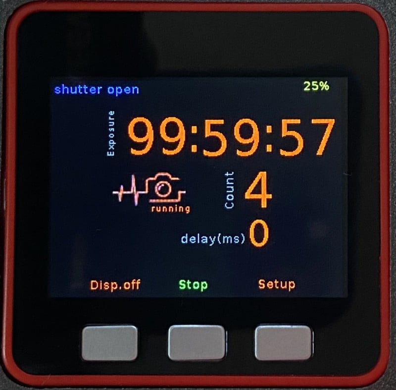
Shutter Open
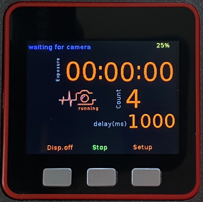
Waiting for Delay
My Olympus E-M10 for instances needs a 450ms delay to get consistent timings under 60 seconds. An Exposure always starts with the set delay.
Download
All downloads can be found on my GitHub for this project: click here.
Video
To show timy in action, here is a way too long video about remote timers and of course about timy. Bonus: USB charging madness.
Final Thoughts
If you have any questions about timy, suggestions, feature requests or if you want to show your builds of timy, feel free to leave a comment.
About the author: Dirk Essl is an IT Solution Architect working for a German television network. He’s not a programmer, but he likes writing software if something that he needs is not available. He also runs the caffenol blog and the largest caffenol community on the Web.
You can see more of his work on his website, or by following him on Facebook and YouTube. This article was also published here.
Continue reading...